Temperature
Elements (Sensors/Detectors) and Transmitters
Types of Temperature Elements:
Filled Thermal Systems
Units Of Temperature Measurements
°C – degrees Celsius (or Centigrade)
°F – degrees Fahrenheit
K – Kelvin
R – Rankine
Relationship between different units
°C = (°F - 32)/1.8
°F = 1.8 x °C + 32
K = °C + 273.15
R = °F + 459.67
°C and °F are the most commonly used unit in our industry.
Units conversion factors will be used from relationship between different units. (above)
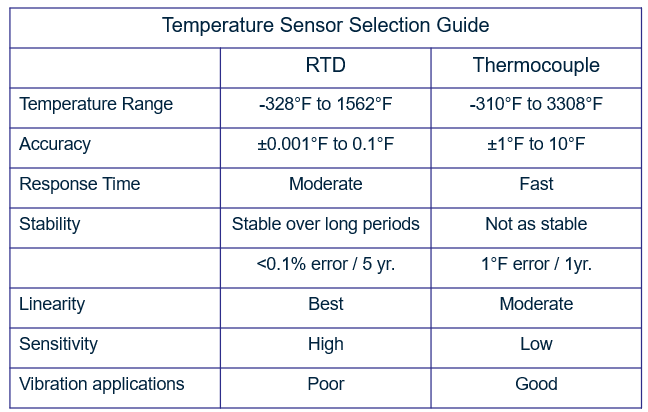
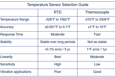
Temperature Element selection : It depicts the various features of RTDs and thermocouples, which can benefit in sensor selection.
Thermocouples have a wider temperature range than RTDs, although RTDs are more accurate.
RTDs are more stable, linear, and sensitive than thermocouples, although they have a longer response time.
In vibration applications, thermocouples are the ideal option.
The thermoelectric effect, which is the foundation of contemporary thermocouple technology, was discovered in 1821 by a German physicist by the name of Seebeck. He noticed that if the two junctions of two dissimilar metals are at different temperatures, an electric current will flow in a closed circuit.
The metals utilized and the temperature relationship between the connections determine the thermoelectric voltage generated.
No current flows in the circuit if the two junctions have the same temperature because the voltages generated at each junction cancel each other out.
Because of this, a thermocouple can only monitor the temperature differences between the two junctions, which limits the viable applications for thermocouples.
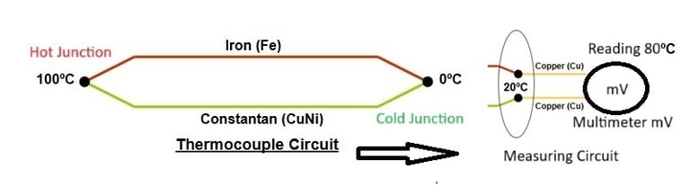
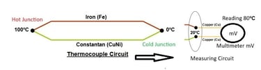
Above Picture shows the industry uses this combination
(J-type thermocouple) extensively.
Heating the measuring junction of the thermocouple produces a voltage which is greater than the voltage across the reference junction.
The difference between the two voltages is proportional to the difference in temperature and can be measured on the voltmeter (in millivolts). For ease of operator use, some voltmeters are set up to read out directly in temperature through use of electronic circuity
Thermocouple Tips are classifieds in to three type:
Grounded: Suitable for applications involving pressure and corrosion. enhanced heat transfer, which results in a faster reaction time than ungrounded.
Response time:
1.00 Second's @ 0.25Inches
~0.60 Second's @ 0.18Inches
Ungrounded: For applications involving pressure and corrosion. response time that is slow. provides electrical separation.
Response time:
2.25 Second's @ 0.25Inches
1.88 Second's @ 0.18Inches
Exposed: For applications that are dry, non-corrosive, and not under pressure. fastest reaction time out of the three.
Response time:
0.25 Second's @ 0.25Inches
~0.14 Second's @ 0.18Inches
The metals utilized and the temperature relationship between the connections determine the thermoelectric voltage generated. (Iron and Constantan metal are used to make this basic circuit.)
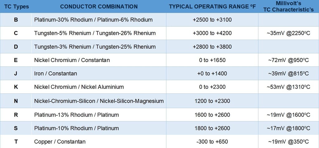
Standard Thermocouple combinations and their operating temperatures in degrees C - Characteristics
The reaction time decreases with increasing probe diameter.

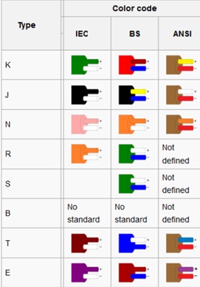
Thermocouple Cable color Coding as per IEC, BS & ANSI standard :
Simple Definition : A thermocouple is an electrical device consisting of two different conductors forming electrical junctions at differing temperatures. A thermocouple produces a temperature-dependent voltage as a result of the thermoelectric effect, and this voltage can be interpreted to measure temperature.
TC-Thermocouple:
Thermocouple Type:
There are several types of thermocouples, each with different characteristics and suitable temperature ranges. The most common types are: K, J, T, E, N, S, R, and B. They are categorized as either base metal (K, J, T, E, and N) or noble metal (S, R, and B) thermocouple
Type K The most widely used general-purpose thermocouple is Type K (chromel–alumel), which has a sensitivity of about 41 µV/°C. The range of its probes is −200 °C to +1350 °C (−330 °F to +2460 °F), and it is reasonably priced. Because Type K was defined during a period when metallurgy was less developed than it is now, sample characteristics may differ significantly.
Type J Compared to type K, type J (iron-constantan) has a more limited range (-40 °C to +750 °C), but it is more sensitive (approximately 50 µV/°C).
Type E Because of its high output (68 µV/°C), Type E (chromel–constantan) is ideally suited for cryogenic applications. It is non-magnetic as well. The wide range is between -50°C and +740°C, whereas the narrow range is between -110°C and +140°C.
Type T made of constantan, a copper-nickel alloy, and copper (Cu). It is well-known for being stable at low temperatures. utilized in low-temperature settings such as ultra-low freezers and cryogenic applications.
Type N The durability and resistance to oxidation of Type N (Nicrosil–Nisil) thermocouples make them appropriate for usage at temperatures ranging from -270 °C to +1300 °C. Sensitivity is marginally lower than type K, at roughly 39 µV/°C at 900 °C.
Type S made up of the platinum-rhodium alloy (PtRh10) and platinum (Pt). used to monitor high temperatures, especially in neutral, oxidizing, and clean environments.
Type R Platinum (Pt) and platinum-rhodium alloy (PtRh13) make up Type R. Type S is comparable, except the positive leg has a somewhat higher rhodium content. Suitable for high-temperature applications, such as heat treating and biotech. More stability and output than Type S
Type B composed of alloys of platinum (Pt) and rhodium (PtRh30 and PtRh6). capable of measuring temperatures as high as 1700°C (3100°F). Less prone to drift and grain development, but with a lower output than Types S and R.
The thermoelectric effect, which is the foundation of contemporary thermocouple technology, was discovered in 1821 by a German physicist by the name of Seebeck. He noticed that if the two junctions of two dissimilar metals are at different temperatures, an electric current will flow in a closed circuit.
The metals utilized and the temperature relationship between the connections determine the thermoelectric voltage generated.
No current flows in the circuit if the two junctions have the same temperature because the voltages generated at each junction cancel each other out.
Because of this, a thermocouple can only monitor the temperature differences between the two junctions, which limits the viable applications for thermocouples.
Above Picture shows the industry uses this combination
(J-type thermocouple) extensively.
Heating the measuring junction of the thermocouple produces a voltage which is greater than the voltage across the reference junction.
The difference between the two voltages is proportional to the difference in temperature and can be measured on the voltmeter (in millivolts). For ease of operator use, some voltmeters are set up to read out directly in temperature through use of electronic circuity
Thermocouple Tips are classifieds in to three type:
Grounded: Suitable for applications involving pressure and corrosion. enhanced heat transfer, which results in a faster reaction time than ungrounded.
Response time:
1.00 Second's @ 0.25Inches
~0.60 Second's @ 0.18Inches
Ungrounded: For applications involving pressure and corrosion. response time that is slow. provides electrical separation.
Response time:
2.25 Second's @ 0.25Inches
1.88 Second's @ 0.18Inches
Exposed: For applications that are dry, non-corrosive, and not under pressure. fastest reaction time out of the three.
Response time:
0.25 Second's @ 0.25Inches
~0.14 Second's @ 0.18Inches
The metals utilized and the temperature relationship between the connections determine the thermoelectric voltage generated. (Iron and Constantan metal are used to make this basic circuit.)
Standard Thermocouple combinations and their operating temperatures in degrees C - Characteristics
The reaction time decreases with increasing probe diameter.
Thermocouple Cable color Coding as per IEC, BS & ANSI standard :
Simple Definition : A thermocouple is an electrical device consisting of two different conductors forming electrical junctions at differing temperatures. A thermocouple produces a temperature-dependent voltage as a result of the thermoelectric effect, and this voltage can be interpreted to measure temperature.
TC-Thermocouple:
Thermocouple Type:
There are several types of thermocouples, each with different characteristics and suitable temperature ranges. The most common types are: K, J, T, E, N, S, R, and B. They are categorized as either base metal (K, J, T, E, and N) or noble metal (S, R, and B) thermocouple
Type K The most widely used general-purpose thermocouple is Type K (chromel–alumel), which has a sensitivity of about 41 µV/°C. The range of its probes is −200 °C to +1350 °C (−330 °F to +2460 °F), and it is reasonably priced. Because Type K was defined during a period when metallurgy was less developed than it is now, sample characteristics may differ significantly.
Type J Compared to type K, type J (iron-constantan) has a more limited range (-40 °C to +750 °C), but it is more sensitive (approximately 50 µV/°C).
Type E Because of its high output (68 µV/°C), Type E (chromel–constantan) is ideally suited for cryogenic applications. It is non-magnetic as well. The wide range is between -50°C and +740°C, whereas the narrow range is between -110°C and +140°C.
Type T made of constantan, a copper-nickel alloy, and copper (Cu). It is well-known for being stable at low temperatures. utilized in low-temperature settings such as ultra-low freezers and cryogenic applications.
Type N The durability and resistance to oxidation of Type N (Nicrosil–Nisil) thermocouples make them appropriate for usage at temperatures ranging from -270 °C to +1300 °C. Sensitivity is marginally lower than type K, at roughly 39 µV/°C at 900 °C.
Type S made up of the platinum-rhodium alloy (PtRh10) and platinum (Pt). used to monitor high temperatures, especially in neutral, oxidizing, and clean environments.
Type R Platinum (Pt) and platinum-rhodium alloy (PtRh13) make up Type R. Type S is comparable, except the positive leg has a somewhat higher rhodium content. Suitable for high-temperature applications, such as heat treating and biotech. More stability and output than Type S
Type B composed of alloys of platinum (Pt) and rhodium (PtRh30 and PtRh6). capable of measuring temperatures as high as 1700°C (3100°F). Less prone to drift and grain development, but with a lower output than Types S and R.
RTD-Resistance Temperature Detector
RTD working Principle : it is working on Ohm's law states that the voltage or potential difference between two points is directly proportional to the current or electricity passing through the resistance, and directly proportional to the resistance of the circuit.
RTD operates under the principle that the electrical resistance of certain metals increases and decreases in a repeatable and predictable manner with a temperature change. As the temperature increases so does the resistance.
R = V/I Resistance is equal to voltage divided by current
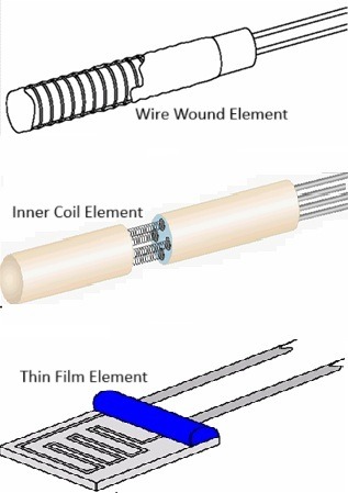
RTD Element Construction: There are three types of RTD constructions.
Wire Wound Element RTD, precise lengths of wire are wrapped around a ceramic mandrel and then inserted into a ceramic shell that functions to support and protect the wire windings.
Inner Coil Element RTD wires are coiled and placed into ceramic insulator holes. Some producers fill the bores with ceramic powder after inserting the coils. This prevents the coils from shorting against one another.
Thin Film Element RTD, In Thin Film Element RTD, metallic ink is placed over a ceramic substrate. Lasers then etch the ink, creating a resistance route. The entire assembly is encased in ceramic to provide support and protection.

RTD Lead wires Construction: There are three types of RTD Lead wires constructions.
Two-wire: Should only be used with very short runs of lead wire. No compensation for lead wire resistance.
Three-wire: Most commonly used for industrial applications. Lead wire compensation.
Four-wire: Laboratory use historically, moving more into industrial applications. Full compensation for lead wire resistance.

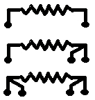
Two-wire
Three-wire
Four-wire
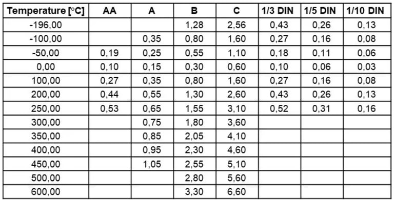
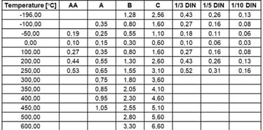
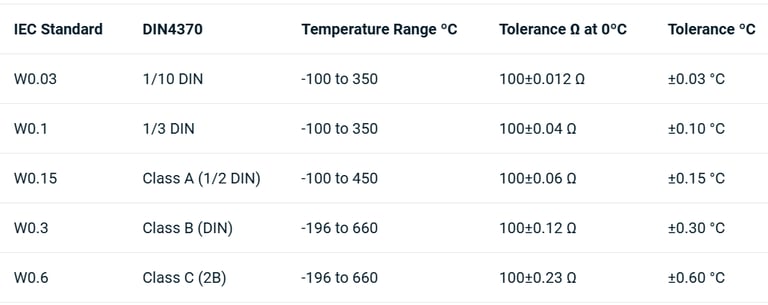
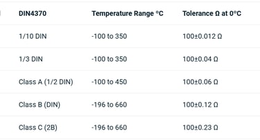
RTD Accuracy Classifications :
The standard DIN EN 60751:2009 is based on IEC 60751:2008. These standards specify the accuracy classes for Pt100 resistance: AA, A, B, and C. Prior to the modification, the most accurate class was A, and all other more accurate classes were classified as non-standard and separated into class B values.
1/3 DIN is based on Class B with a divided value. This means that the 1/3 DIN is not relevant across the entire measuring range. This discrepancy in precision is only established at the points where 0°C = +/- 0.3°C and 3°C = +/-0.1°C. As previously indicated, this class is not standardized.
1/10 DIN is also based on Class B and does not apply across the entire range. This accuracy is solely determined at the point 0°C = +/- 0.3°C and 10°C = =/-0.03°C. The Class B 1/10 DIN is not standard.
Class A : accuracy is +/- 0.15 °C at 0°C ( PT100 )
Class B : accuracy is +/- 0.30 °C at 0°C ( PT100 )
Class C : accuracy is +/- 0.60 °C at 0°C ( PT100 )
Class AA : accuracy is +/- 0.10 °C at 0°C ( PT100 ) It is equaling to 1/3 DIN i.e., +/- 0.1°C
1/3 DIN : accuracy is +/- 0.10 °C at 0°C ( PT100 ) It is equaling to 1/3 DIN Class-B ( 0.3°C / 3 = +/- 0.1 °C ).
1/5 DIN : accuracy is +/- 0.06 °C at 0°C ( PT100 ) It is equaling to 1/5 DIN Class-B ( 0.3°C / 5 = +/- 0.06 °C ).
1/10 DIN : accuracy is +/- 0.03 °C at 0°C ( PT100 ) It is equaling to 1/10 DIN Class-B ( 0.3°C / 10 = +/- 0.03 °C ).
RTDs are most typically made of platinum and are also known as Platinum Resistance Thermometers, or PRTs for short.
At 0°C, the resistance is 100Ω, hence it called as "PT100".
The temperature coefficient for a PT100 sensor is at 100°Celsius, their resistance is 138.5Ω, hence the fundamental interval of 38.5Ω or 0.385Ω per 1°Celsius rise in temperature
Other materials, such as Germanium, are available for more unusual temperature ranges (10 to 100°Kelvin).
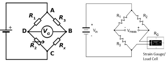
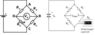
The Wheatstone bridge circuit is the most often used method for measuring an RTD's resistance. In a Wheatstone bridge, electrical excitation current passes across the bridge, and the bridge output current indicates the RTD resistance.
A simple circuit for measuring an unknown resistance by connecting it so as to form a quadrilateral with three known resistances and applying a voltage between a pair of opposite corners
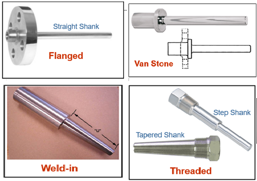
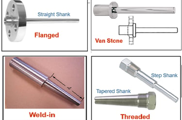
Thermowells :
Most used thermowells are Flanged, Threaded, Van Stone and Weld-in.
The flanged kind is the most popular. It is employed in high-pressure applications where well removal is required.
The Van Stone is a subtype of the Flanged.
Threaded is favored in non-hazardous, low-temperature, low-pressure applications when well removal is not required frequently.
The weld-in type is employed in high-temperature, high-pressure applications such as steam services. and used where well removal is not required
There are two types of shanks used : straight, tapered, and Step.
The tapered and step shanks allow better heat transfer (and consequently faster response) than the conventional straight shank. The tapered shape also outperforms the straight variety in high fluid velocity applications because to its higher rigidity.
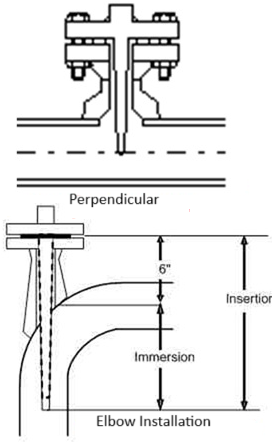
Thermowells must be carefully selected for processes with high velocity.
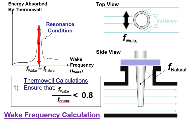
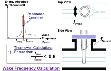
The thermowell is subjected to the flow's tension and friction after penetrating it. This may cause a natural vibration, resulting in the shearing of the thermowell into the process. This is known as the "Wake Frequency".
ASME PTC 19-3 - Thermowells: This Standard sets a mechanical design standard for the reliable operation of thermowells in a wide range of applications. This comprises an assessment of the forces created by external pressure, as well as the static and dynamic forces produced by fluid impingement.


The temperature coefficient (indicated by the Greek letter Alpha => α) of the Pt100 sensor is the difference between the resistance at 100°C and 0°C, divided by the resistance at 0°C multiplied by 100°C.
The formula is pretty simple, but it does sound a bit complicated when written, so let’s look at it as a formula:
α = ( R100 -R0 ) / ( R0 *100 Deg C )
Where:
α = temperature coefficient
R100 = resistance at 100°C
R0 = resistance at 0°C
Let’s take a look at an example to make sure this is clear:
Pt100 has a resistance of 100.00 ohms at 0°C and a resistance of 138.51 ohms at 100°C. The temperature coefficient can be calculated with the following equation
α = (138.51 Ohms - 100.00 Ohms) / ( 100.00 Ohms * 100 Deg C)
We get a result of 0.003851 /°C.
Or as it is often written: 3.851 x 10⁻³ °C-1
Often this figure is rounded and the sensor is referred to as a “385” Pt100 sensor.
This is also the temperature coefficient specified in the IEC 60751:2008 standard.
Thermistor's
Similar to RTDs, thermosistors are temperature detecting devices whose resistance varies with temperature.
The main distinction is that most thermistors experience a decrease in resistance as the temperature rises.
When the temperature range is less than 150°C, thermoistors are a cost-effective substitute for RTDs. Temperatures between -80°C and 300°C are suitable for using thermoistors.
The base resistances of the majority of thermistors are significantly higher than those of RTDs.
A thermistor sensor's ability to modify resistance significantly in response to a very minor temperature change is one of its biggest benefits. Because of this, they are extremely sensitive to even slight temperature changes.
thermometer bulb), a signaling or recording device, and a way to connect the two.
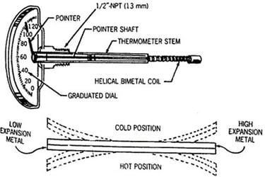
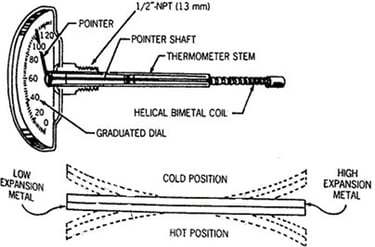
The two metals' different thermal expansions are what produce coil spinning. The revolving coil has a pointer attached to it that shows the temperature on the dial.
Here's a simple illustration: As the temperature varies, two metal strips expand at different rates.
Temperature Transmitter:
It means a signal Conditioner from a low signal to High signal. it is also called as a Transducer (One form of a energy/signal to another form of a energy/signal)
Low Signal Means mv ( thermocouple signal) or Ohms ( RTD signal)
High Singla means transmitter signal that is 4-20mA
or Digital signal ( Foundational field bus).
Duplex Transmitter : Transmitter compatible for Duplex sensor, if there is any sensor failed it will automatically changes to healthy sensor. ( it called Hot standby or Hot backup enabled transmitter)